Description
Detailed Technical Analysis
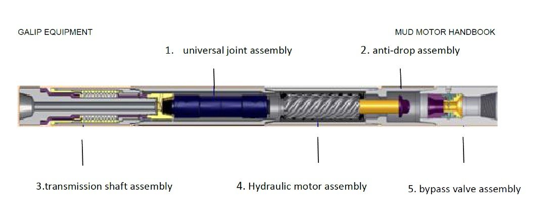
1. Universal Joint Assembly (U-Joint)
- Role: Acts as a specialized connector, translating the eccentric planetary motion of the rotor into the pure, concentric rotation required by the downstream transmission shaft.
- Maintenance: Subject to high stress due to continuous pivoting and rotation; requires frequent inspection to prevent joint failure and tool breakage.
2. Anti-Drop Assembly (Safety Section)
- Role: A critical safety device to prevent loss of the entire motor/bearing section downhole if the casing below it breaks or decouples.
- Activation: Casing failure causes the internal screw components to drop slightly until a large circular nut seats onto a reduced diameter section. This mechanical seating action blocks the mud channel, causing an immediate and noticeable increase in pump pressure at the surface, which serves as a timely warning to the drilling crew.
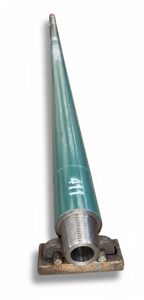
3. Transmission Shaft Assembly (Bearing Section)
This assembly handles the mechanical stress transferred to the drill bit.
- Role: Transmits the concentric rotary motion to the drill bit and absorbs all axial (WOB) and radial loads.
- Bearing Systems (Based on ΔP):
- Lower ΔP (e.g., 3.5 MPa): Uses needle roller bearings for radial support and a thrust ball bearing for axial support.
- Higher ΔP (e.g., 7.0 MPa): Employs hard alloy radial bearings and a series of thrust bearings to maximize wear resistance and load capacity.
4. Hydraulic Motor Assembly (The Power Section)
This is the core component that relies on the Progressive Cavity Principle.
- Composition: A helical Rotor (with X lobes/heads) is fitted eccentrically inside a stationary helical Stator (with X+1 lobes/heads, typically lined with rubber).
- Working Principle: The meshed profile creates a series of sealed cavities along the axial lead. Drilling mud, under pressure, forces the rotor to make an eccentric revolution and self-rotation as the cavities move the fluid downward, converting pressure energy into mechanical energy.
- Performance Parameters:
- Torque is directly proportional to the motor’s pressure drop ΔP).
- Rotational Speed (RPM) is directly proportional to the input mud flow rate (Q).
- Lobe Ratio (X: X +1): Controls output characteristics. Fewer lobes (1:2 or 3:4) yield High Speed, Low Torque (suitable for soft formations); More lobes (5:6 or 9:10) yield Low Speed, High Torque (suitable for hard formations).
- Pressure Management: The pressure drop per motor stage (one lead) should ideally not exceed 8 MPa to prevent motor damage (leakage, seizing, and excessive wear).
Torque ∝ ΔP motor and RPM ∝ Q mud
5. Bypass Valve Assembly
- Role: Manages the BHA internal pressure and flow path, connecting the drill string to the annulus when static.
- Operation:
- Closed (Drilling): High mud pressure overcomes the spring force, pushing the valve core down, closing the bypass hole, and forcing all mud into the motor.
- Open (Pump Off): Low fluid pressure allows the spring to push the valve core up, opening the bypass to connect the drill column with the annular space (the wellbore), preventing pressure contamination and facilitating faster tripping.
Performance Parameters of the Screw Drilling Tool
| Specification | 5LZ95x7.0-4 | 7LZ102x7.0-5 | 5LZ120x7.0-4 | 7LZ127x7.0-5 | 5LZ165x7.0-5 | 7LZ172x7.0-5 | 7LZ203x7.0-5 | 5LZ216x7.0-5 | 5LZ244x7.0-5 | |
|---|---|---|---|---|---|---|---|---|---|---|
| OD | 3 ¾” | 4” | 4 ¾” | 2” | 6 ½” | 6 ¾” | 8” | 8 ½” | 9 5/8” | |
| Bit Size | mm | 118~152 | 118~152 | 149~200 | 149~200 | 213~270 | 213~311 | 251~346 | 251~346 | 311~444.5 |
| in | 45/8~6 | 45/8~6 | 57/8~77/8 | 57/8~77/8 | 83/8~105/8 | 83/8~121/4 | 97/8~135/8 | 97/8~135/8 | 121/4~171/2 | |
| Lobe | 05:06 | 07:08 | 05:06 | 07:08 | 05:06 | 07:08 | 07:08 | 05:06 | 05:06 | |
| Stages | 4 | 5 | 4 | 5 | 5 | 5 | 5 | 5 | 5 | |
| Differential Pressure | Mpa | 4.8 | 5 | 5.4 | 6.0 | 6.6 | 6.0 | 7.0 | 6.0 | 6.0 |
| Psi | 696 | 725 | 783 | 870 | 957 | 870 | 1015 | 870 | 870 | |
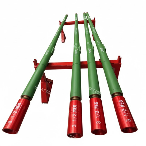
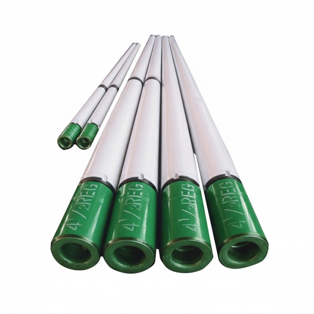
| Connection | Front end | 31/2REG.Box | 31/2REG.Box | 31/2REG.Box | 31/2REG.Box | 41/2~65/8REG | 41/2~65/8REG | 65/8REG.Box | 65/8REG.Box | 65/8REG.Box |
| rear-end | NC31.Pin | NC31.Pin | NC38.Pin | NC38.Pin | NC50.Pin | Nc50 / 51/2 FH | 65/8 FH / REG | 65/8 FH / REG | 65/8 FH / REG | |
| Flow Rate | LPM | 300~720 | 350~750 | 600~1080 | 600~1140 | 1080~1680 | 1200~2160 | 1800~3900 | 1920~3000 | 2400~3600 |
| GPM | 80~190 | 93~198 | 159~285 | 159~301 | 285~444 | 320~576 | 480~1040 | 512~800 | 640~960 | |
| Bit Speed | r/min | 110~260 | 92~210 | 126~227 | 100~189 | 106~165 | 85~160 | 85~160 | 105~163 | 95~140 |
| Torque | Nm. | 1428 | 2620 | 3100 | 4380 | 9360 | 10400 | 13920 | 14190 | 19600 |
| Ft-lbs. | 1054 | 1934 | 2288 | 3232 | 6908 | 7675 | 10272 | 10472 | 14465 | |
| Max.Torque | Nm. | 2142 | 4080 | 4650 | 6445 | 13210 | 15600 | 20880 | 21260 | 29400 |
| Ft-lbs. | 1579 | 3011 | 3430 | 4756 | 9749 | 11505 | 15450 | 15690 | 21697 | |
| Weight on Bit | KN | 25 | 25 | 40 | 50 | 100 | 100 | 170 | 180 | 180 |
| Lb. | 5500 | 5500 | 8800 | 11000 | 22000 | 22000 | 37400 | 39600 | 39600 | |
| Output power | Kw | 18~64.8 | 28.8~67 | 30.2~53.8 | 49.2~97.2 | 108~168 | 122~182 | 121~212 | 154~240 | 160~240 |
| HP | 24.1~86.8 | 38.6~89.7 | 40.4~72 | 65.9~130.2 | 145~225 | 164~244 | 162~284 | 206~322 | 214~322 | |
| Length | 1.75°/mm | 3700 | 4300 | 5600 | 6300 | 7800 | 8200 | 8300 | 8500 | 9188 |
| Weight | Kg | 182 | 216 | 524 | 615 | 987 | 1040 | 1565 | 1666 | 2289 |


Reviews
There are no reviews yet.